Updated May 12, 2013
Problems with the Electro Rangefinder Camera can frequently be solved that do not require sophisticated test equipment or tools. None of the information provided here will be found in Yashica's repair manual. If you intend to buy a junker for parts, there is an outside chance that even within a specific model, that some parts may appear as slightly different or do not interchange. Trying to change the entire lens assembly often results in a mismatch of electronic parts that you will then need to match up. Copyright to the Text and Images is enforced by me.
You may scroll the page [ recommended ] or click on a heading to jump directly to a paragraph. The topics that are dealt with include:
Testing for Erratic Exposure
Restoring good electrical contact in general and specifically after a battery leak.
Checking the electrical contact between the battery compartment spring and the electronics.
Removing the top plate, required for several repairs.
Setting up or reassembling the ASA Speed Dial
Cleaning or replacing the viewfinder glass
Adjust Rangefinder Infinity Setting
Upgrade G, GS, GT to GSN /GTN
Replace Battery Check Switch
Replacing the 'Pad of Death'
Release Stuck Frame Counter
Replacing the original foam light seals which deteriorate, causing many problems.
Access to Front Lens Element
Restoring a snap button face on the camera case.
The Easy Way Out or... If all Else Fails
Erratic Exposure Test: A primary cause of erratic exposure occurs when the lube in the shutter dries and gums up the works. One simple test for this is to attach a strobe flash to the camera, and fire several shots to see if the flash goes off each time. You do not need film in the camera to wind the shutter. Set the shutter at AUTO and proceed. In the "G" series of cameras, the flash will not fire until the shutter blades reach their extreme outer travel limit. A shutter with bad lube will only sometimes if ever fire the flash, so you have now pinpointed the most likely cause of the problem.
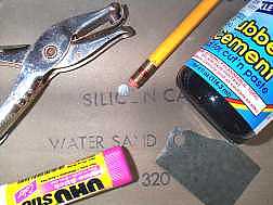 Electrical Contact: Establishing a good electrical contact by cleaning the battery compartment screw-in cap is quite straight forward because you have access to it. Cleaning the internal spring contact area if it doesn't appear to be bright, need not be a challenge either. Most of what is required to do a professional job may already be within easy reach.
Use a hand or letter punch to cut a small disk out of a sheet of 320 Grit Silicone Carbide Sandpaper. Attach this disk to the eraser end of a pencil using rubber cement or a glue stick. You can now easily remove light tarnish from the area of the internal spring in the battery compartment with ease. Don't overdo it!
If the battery compartment and screw in cap have fallen victim to a battery leak proceed as follows. With a cotton swab moistened lightly with white vinegar, clean up the spiral spring, or any other internal area where residue can be spotted. You will most likely need to switch ends and use more than one bud to clean this up. Be patient! Then daub the area with a clean water bud. The battery cap itself can be immersed in vinegar for a while, using a bottle cap or other small container. A cotton bud will then clean up the contacts nicely. Use a sheet of paper to work between the spring contact ring and the surface of the cap. You want to get rid of all traces of this corrosive residue. A wooden toothpick will help to get into tight spaces. Rinse with plain water and allow to dry thoroughly.
If you have encountered a camera that has not been in use for a very long time, it is possible that it may contain a battery leakage of such proportions, that the battery cap cannot be unscrewed using an amount of force consistent with not damaging the camera.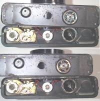
In this case the course of action is not to be tempted to use brute force, but to remove the base plate. There are only 3 Phillips head screws which secure the base plate. Use a precision #3 Phillips Screwdriver [2mm] . This work should be done where there is no chance of the removed screw falling down and disappearing. Go on the assumption that a battery is installed, and still under spring pressure. Hold the plate firmly in place particularly as you remove the last screw, or it may go flying off, never to be seen again! If any screw offers enough resistance to possibly strip the head, don't force it further. Try applying a drop of penetrating oil and let it soak for a few hours. If that doesn't help, apply a soldering gun at high heat to the screw head for a minute.
It now becomes possible to soak the base plate in a glass of vinegar, which will eventually permit the screw-in cap to be removed and the clean up to begin. The camera on the left is a black body Yashica MG-1 showing before and after treatment. As it turned out, the battery had to be forcibly removed. Note that the contactor ring on the camera was also accessible for cleanup, which would not be the case if the base plate had not been removed.
A number of site visitors have suggested that emphasis be placed on how much easier it is to use a magnetized screwdriver. Lightly rubbing a tool against a magnet will transfer some magnetism to it. This keeps the tiny screw attached to the driver when withdrawn from the work so there is less chance of it falling and getting lost, and is a great help in holding a screw in place on the driver while putting it back. Working close to your table will also reduce the chance of small parts bouncing off the surface never to be seen again.
Testing Spring Contact. There is no contact between the - Negative or + Positive battery terminals and the Yashica Electro camera body. The path to the camera body is reserved for one side of the Flash terminal. To determine if the spring inside the battery compartment is conducting to the electronics, you need to run a test lead from the spring to a negative terminal. This is easily accomplished by removing the Test Button frame, taking care not to loose the tiny 2 screws, or the push button which is free to fall out. Take the extra moment to apply a piece of tape over test button to secure it in place. This will also help when the time comes to reinstall the assembly. Use a magnetized screwdriver. The picture shows the terminal to which 2 white wires are connected on the circuit board. This is the point to which a test lead from the spring is run. If you are using an ohm meter, there should be Zero resistance if all is well. If using a lamp continuity tester, the lamp should come on at full brightness. The battery compartment is installed at the factory with the spring passing right through the plastic at the bottom of the battery compartment. The wire to the circuit board is soldered to this part of the spring. Removing the screws on top of the battery compartment will NOT permit you to remove the battery holder as there is no slack in the connecting wire soldered to it.
Removing the Top Plate. The removal of the top plate is required to clean the viewfinder, replace lamps and other procedures. Here's how. Step one is to unscrew the battery test-switch frame from the rear of the top plate. Use of a magnetized screw driver will help to the hold onto the screws, and ease their later replacment. The red test button is loose and will fall out. Keep all parts in a dish which will not tip over. If you allow any of these tiny items to fall off your work top, you may never find them again! keep track of the sequence of the parts as you remove them. Talking into a tape recorder is a good idea.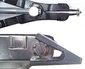
The next step is to remove the ASA Speed Dial and the Film Advance Lever. The safest way to remove these without scratching up the fittings, is the use of an Adjustable Snap Ring Pliers. These pliers are usually used to handle "C" clips and should come with a set of several size points, both straight and angled. The points are interchangeable and the set required is .039 inch. They can be turned so that they point straight down when the correct distance between them has been set. Sources are auto supply and hardware stores, although anyone who works on automobiles or electric motors will likely have one. Turn counter clockwise to remove the screws. Little effort is required. Use minimum force when reinstalling the dial and lever assemblies. If the pin-hole head screw holding the wind lever offers high resistance, don't force it ! Apply a soldering gun at high heat to the screw head for a minute to break the bond. This large head can exert a lot of torque on the very thin screw thread it is attached to and could snap off if you go at it like a bull in a china shop.
The next step is the removal of the rewind knob assembly. A Wedge should be used to get a good grip without damaging the finish of the knob. The image shows a homemade wedge cut out of a scrap of plastic, but hard-wood can serve the same purpose. A strip of rubber from a tire tube has been glued to the inside using crazy glue [cyanocrylate].
To remove the rewind knob, open the rear door of the camera, and insert a firm strip between the fork of the rod that engages the film cassette. Try to find something that will not scratch if it reaches down too far. Holding the strip firmly, unscrew the rewind knob counter-clockwise. Not much force is required. There is a small washer between the rewind shaft and the knob. Tape it to the knob when it is removed for safekeeping. Take note of the sequence of all the parts as you remove them in the next steps. Now you are ready to remove 1 screw from each end of the the top plate, and 1 at the rear below and to the right of the test switch position.
Do Not Remove these parts: Shutter release knob & assembly, PC flash socket, shoulder strap anchors, exposure lamp cover, viewfinder or any other front or rear trim plates. With the MG-1 in addition to the foregoing, do not attempt to remove the Flash / Auto Lever. It will come away with the top plate.
The top plate can now usually be be lifted off with ease. Grip the camera body firmly, do not hold the lens. It is helpful if one person grips the body while the other lifts the top plate. On occasion, cement which is used to apply the black skin to the camera, will have run over the edge that fits under the lip of the top plate. This may make the top difficult to lift. In this case, place a wide piece of aluminum or copper up against the rim and give it a sharp tap. Do not use a screwdriver. The blade is too narrow and hard and may cut into the top plate. Be sure to keep control of the top plate travel as it is removed. If the glass is damaged be sure to first place a piece of tape over, it to avoid it from shattering. The GSN /GTN model will have a wire connected both to the Hot Shoe and the PC socket. Other models will have only one wire connected to the PC socket. Avoid tearing these loose as you remove the top plate. To do any meaningful work on the camera the connecting lead/s need to be disconnected using a pencil soldering iron.
Assembly and Lining up the ASA Speed Setting Dial:
Place the outer chrome ring on the keyway of the speed control shaft so that the notch in the ring lines up with the smallest opening in the diamond shape iris in the Light Sensor window when the notch indicator on the ring is at the 4 o'clock position [ as viewed from the rear of the camera so that 'Electro 35' reads correctly ]. This sensor window is on the top front left located directly below the Film Advance Lever.
Now place the spring washer on that same post, and locate the inner dial plate [ that has the ASA film speed numbers ], in such a way that the lowest number is directly centered to the indicator notch of the outer ring. Depending on the camera model, this number is usually 25 but may be 12.
When you have this lined up, get a good adhesive tape that won't leave a residue, and tape the inner ASA speed dial to the outer ring, being careful not to cover the center of the dial that the pin-head screw will contact. Now fasten the pin-head screw that holds down the ASA dial firmly.
Gently remove the tape, and then turn the outer ring opposite to the highest number on the dial. Check the front Diamond shape Iris in the light sensor window to make sure that it is at it's maximum opening. If not start over as you may have had some slippage. Unfortunately the dial is only held in place by the pressure of the small spring washer under it, as the outer ring must be free to travel on the shared mounting post, so avoid touching the inner speed dial while setting the ASA / ISO speed. This Dial Plate should not move when the outer setting ring is being turned.
Glass Removal: The frames holding the 2 glass windows are retained with one small wedge clip each. A liberal amount of cement keeps these from sliding out of place. If a glass needs to be replaced, the cement at the forward edge of the clip along the top plate, should be scraped away.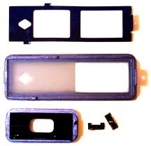 During removal, a length of tape should then be run across this very tiny clip to prevent it from flying off into space, never to be seen again. To remove the clip, slide a small pointed awl or nail into the space left between the angle of the clip and the frame. To replace a cracked glass, unscrew the black shield from the frame and slide the shield out along it's length. When the glass is lifted out, a cardboard template can be made which is a precise fit for the purpose of cutting a new glass. If this is not within your scope, have a picture framer or window glass firm do this for you. Determine if they have the ability to frost the required portion of the new glass to the exact pattern of the original. If they are unable to do this ask for suggestions as to who might have a sandblaster. You will of course have to provide the glass with the correct protective mask on the portion that needs to be kept clear. Be sure to mask the diamond which must remain clear. If sandblasting or acid treatment is out of the question, apply a piece of frosted acetate sheet to the inside surface of the glass with the diamond pattern cut out. Acetate sheets are available from art supply and even some office supply stores.
Locating the Diamond: In the event that the finder glass is broken and you need to position a matte of the diamond precisely, place the new clear glass in the frame and simply lay the mask over it. A layout taken directly as measured from the edge of the glass itself to the nearest diamond point is: 3 mm from near end of glass, 4.5 cm from the far end of glass, and 5 mm from both the top and bottom edges.
Removal & Cleaning of the Finder Assembly: To gain access to optics as well as the 2 screws which attach the finder assembly to the body, the top cover of the finder needs to be removed.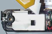 Do not attempt to bend or pull this up as the metal is very brittle. Run a blade around the outer edge to loosen the cement. Under NO circumstances should you attempt to clean the Beam Splitters which are the diagonal glasses in the assembly. These have a coating which both partially transmits and reflects light. Contact with anything but a puff of air can remove the coating and destroy the camera's rangefinder capability. When replacing the metal cover on the assembly use a water based cement if possible. Model cement or crazy glue give off fumes that may deposit on the glass surfaces and make them slightly hazy.
.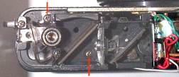
Removing the Finder Assembly:Only two screws hold the entire viewfinder / rangefinger assembly. These screws are indicated by the red arrows. Under no circumstances should any of the other screws in this unit be loosened, unless you are prepared to spend a huge amount of time getting the split image back in alignment. To the far left, you can see the screw that locks the position of the carry strap holder. To the right are the colour masks for the Over / Under exposure indicators, and behind them the 2 lamps. Through the use of an ingenious optical system, these exposure indicators appear as a 'heads up' display directly in front and to the top of, your view through the finder.
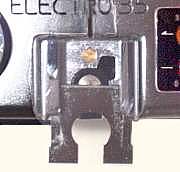 Adjusting the Rangefinder: If the Infinity setting for the lens does not match the Split Image Rangefinder indication, it is possible to make this adjustment without the need to remove the Top Plate of the camera. Be sure to set the focus ring to Infinity. It requires the use of a flat blade screwdriver of at least 2.4mm but with a blade thickness found in a 1.4mm. On some cameras this adjustment screw is so tight, that this shortcut will not work. The Dust Cover on the rangefinder, has a square cut-out as seen in the 2nd image above. By removing a plate on either the cold or hot shoe, access to the rangefinder Infinity adjustment is possible. This plate is barely visible. To remove it, lift the leading edge where the accessory shoe meets the front of the body, with a very small screwdriver. If you look carefully you will see the tip of the screwdriver is wrapped in a width of Scotch Tape. This prevents a scratch in case it should slip. As the hooks at each side of the cover clear the height of the shoe, slide back the cover. This is a good time to clean the center contact of a hot shoe with brass or silver polish.
When pushing the cover back in place, gently press down on each side of the rear end so the bent over flange on the bottom of the cover engages the back of the shoe.
Upgrading your G, GS, GT to GSN / GTN: I received an email from Ron Cram asking if I had any ideas on how he could reliably use a strobe flash with no PC cord on his GS. After some thought, I came up with a solution and shortly received some extraordinary images of the Mardi Gras shot with his Yashica GS with flash. The essential difference between the early G and later GSN is the hot shoe. If you have been following this site, you will know how strongly I feel that the way to optimize flash photography is to use a flash bracket. [see the Tips page]...shhh don't tell anyone, if your mouse happens to stray over that image, the flash will fire! Of course not everyone has a strobe with a cord that can be plugged into the PC socket, so enabling a hot shoe is a reasonably easy and practical solution. Now everyone with a G can own a GSN by following these simple directions..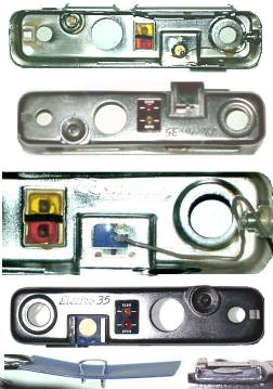 In the sequence of images, the first view is of the underside of the GSN top plate. A single wire running from the PC Socket goes to the centre insulated conductor of the hot shoe. The trigger wire from the shutter to the PC socket has been removed to provide the freedom to shoot this image.
The second image in the row is of a GS that has the 'Dress Plate' covering the flash bracket partly removed. This reveals a Convenient hole in the top plate that was used to get access to the rangefinder setting. The first step in the conversion is to slightly lift the edge of the dress plate facing the front of the camera with a thin bladed screwdriver. It is spring loaded and this will pop it loose and enable you to remove it.
The next step is to cut a thin piece of plastic from the lid or side of a container to a similar dimension as the dress plate, but about 2 mm longer, so that if you slide it into the shoe, it will make contact with the far end ledge that the dress shoe does not. Having this piece butt up against the ledge provides better support and alignment as you go forward into the next steps. For clarity I selected blue plastic but obviously you can get whatever result that you prefer by looking for that colour, or simply painting it with nail varnish or spray paint.
Step two is to slide the new cover plate into position and then mark the centre location that is isolated from the metal frame. There are two possible directions that you can go in. The simplist is to cut a thin strip of metal from the lid of a tin of beans or whatever you have in your recycle bin. Thoroughly remove any paint or finish from this strip to provide good electrical contact and make a clean solder connection possible.
Now cut two slots in your cover that are clear of the camera's top plate and bring the metal strip that has been formed to shape, through the slots as shown on the last image. Press this firmly down, then cut off all but a short piece of the legs from the underside. Fold these down firmly and then cover with a few sheets of paper to protect the finish while for good measure you tap the whole thing as flat as possible with a hammer. You can now solder a connecting wire to the underside that you will run from your new hot shoe to the PC socket. You can see this in the next to last image.
My option was to mark the centre of the new cover plate, punch a small hole it it, and then insert a thumb tack with it's shaft cut off just long enough to poke through, and allow a solder connection to be made to it. The smallest thumb tack that came to hand turned out to be red, but this on close inspection was just a vinyl cover that was easily peeled off. This tack however had a dome top which was too high to permit the flash to slide on. I placed the tack on a piece of metal with a hole for the shaft to face into and then pounded it as flat as possible. For good measure I filed down the leading edge.
After assembling it all, I fitted the flash and made sure the contact to the flash was good and that the underneath contact and wire connection did not short out to the frame. The next step was to remove the flash and the new assembly and coat the bottom of my new plate as well as the metal frame that it would lie on, with contact cement. Crazy glue would probably do too. Do not slide the cover plate into position from the front. Insert one side, then bend down the other side so that it fits under the opposing side slide and press down. Insert the flash gun to hold this in position for a few hours.
Now comes the only hard part. The guide rails on the GS are narrower than the GSN, and therefore may not make contact with the spring loaded terminal on you strobe flash. The Toshiba and Hanimex flash guns that I checked, had contacts on both side. A Vivitar that I only got to look at after the project was completed, had only one side contact, and that, as it turned out, was on the other side of the rail extension that I had made, so check this on your flash gun before proceeding further. To extend the shoe contact out further I made a plate with a single bend that was soldered to the top of the left hand shoe rail as seen in the images. I found it too difficult to work with and form such a small piece of regular sheet metal, so I made a piece big enough to work with and ground it down to size on a belt sander. To solder this in place I removed the plating from the camera shoe rail. Image 3 shows the wiring. Image 4 shows the completed top piece. Image 5 right side shows an end on view of the extended rail. Short out the connection from underneath and see that the flash fires, obviously turn the front away from you. If all is well, then mix up a batch of epoxy and drop a glob over the contact on the bottom which will act as an insulator and lock the thumb tack in place. Do this with the flash gun mounted to press the cover firmly down in place. I have slid a strobe flash on and off at least a couple of dozen times and everything remained in place even without the final epoxy. If anyone has another idea for this process, we sure would like to hear about and post it on this page. Thanks to Lynn Sellers, 'The Yashica Kid' for providing the GS top plate to experiment with.
Replacing The Battery Check Switch: Before attempting to replace a battery check switch, it is helpful to know just what is involved, and unless the switch is shorted and running down the battery, perhaps you may be better off leaving sleeping dogs lie. Even with a shorted switch, it may be easier to simply cut one of the leads running to it. But of course you are determined to fix the problem right.....so here's how.
Following the Steps outlined above, remove the Top Plate and the Rangefinder Assembly. Remove the screw holding the chrome bracket to the Brass Plate that supports the platform on which the ASA dial is attached. Bottom towards right side of camera in image.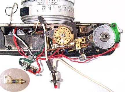 Loosen the bottom screw of the chrome bracket, then rotate it away from the brass mount, turning it counter clockwise until it faces straight back and overhangs the rear of the camera. Fasten that bottom screw. This keeps the spring out of the way. Gently hook back the spring and release the two red wires which were kept neatly in place by the spring. In order to be able to reach the two screws that hold the test switch in place, the circuit board must be free to move somewhat. The Over Under light assembly seen to the left, which is projected into the viewfinder, has to be removed with care. All screws holding the circuit board need to be removed. When the 2 screws holding the test switch are accessable with a long thin screwdriver, undo the switch and unsolder it.
The white wire coming from the access to the lens will need to have an extension soldered to it. The original wire from the circuit board to the switch should also be desoldered from the board. A longer replacement wire will be soldered to the switch to make the new installation easier. These two replacement wires can clearly be seen because much heavier guage wire has been used purely for the purposes of this illustration. Try to use the same size wire as you need the flexibility.
The replacement switch was a stock item easily located in electronics / radio parts stores. It does not have the mount of the original which can be seen in the image insert. [ If you look carefully you can see the green corrosive battery acid that has somehow deposited itself inside the switch destroying the contacts. One of it's terminal posts was also similarly destroyed. ] The new switch secures in place primarily because it is trapped, but cement is used liberally. Two washers were used. One face of the washers was cut off flush to allow the switch to fit as snugly as possible in the conveniently existing slot in the circuit board. It was calculated that this would bring the pushbutton into precisely the same relative position as the original. The switch was put in place. All screws were then replaced. 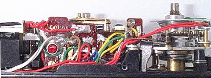 The Lamp Assembly was secured in place and the Rangefinder installed. The Top Cover plate was then put in place.
Unfortunately it turned out that when the cover plate with the external test button was lined up sideways to see the clearance, it was obvious that the post on the new switch extended too far. There is no clearance to add another washer to position the switch further back, so we melted down the face of the post on the new switch with a soldering iron, very carefully, a bit at a time, until it was possible to install the test cover plate and it's button in place, and have the switch activated exactly as it would have originally, with a factory part in place.
The Top Plate was now removed and the Brown wire to the PC socket was soldered on. The camera is ready to assemble! Be sure that you do not pinch any wires when replacing the Top Plate. The lower image shows the completed installation. Some GSN circuit boards have a component which obstructs a large diameter switch like the one used here. You really need to search out a momentary contact switch closer to the size of the original.
James Somners has been kind enough to document the repair of the test switch for those living in areas where a replacement part may be hard to come by. His report follows....
If you are adventuresome, or just cheap, the original switch is simple and with care can be salvaged. The failure point, is where the wire attaches to the internal spring. This will be indicated by the green corrosion, and likely a disconnected wire.
TIP: If you are going to salvage the switch, you will need wire the same size, bigger will NOT work. As suggested elsewhere on this site, stranded telephone wire is the right size. If you don't have that, carefully scavenge the wire from the other side of the switch with the clear plastic sleeve on it (save this sleeve). Do not cut the wire, but unsolder it carefully and quickly with a pencil iron. Be careful not to touch the plastic on the switch or spend much time with heat on the contact. The plastic is fragile and will easily melt. Take the bottom plate off and make note of where the wire goes to the little circuit board next to the battery compartment. Unsolder it. We unsolder this, as the wire is old. Where it has been soldered, it should be usable. Cutting and stripping the wire to length won't work easily, as the internal strands are hard to solder to due to the age of the wire.
The switch has even smaller parts inside it, that are critical not to loose. Put down a microfiber towel to keep everything in check. Looking at the end on the switch, you can see a little star retainer. Carefully grab the contact pin with some needle nose pliers and pull it out straight. If you break the body, you might still be able to save the switch with some heat shrink. But at that point, you really should replace it. The spring will likely come out with the pin and retainer, be careful not to loose it. Take a note of the direction it comes out. One end uses a stretched out coil to attach to the wire. This is where it will fail.
The spring will need to be cleaned of the green corrosion. To super clean copper, use a small clear glass (like a brandy glass) and pour half an inch to an inch of white vinegar into it. Add in a teaspoon or two of salt. The salt reacts with the vinegar to quickly dissolve the corrosion. Stir the salt in until it is well dissolved. Toss the spring in. Give it a swirl every few minutes. It will not take long to clean it, 15-30 minutes.
Finish taking the switch apart. There is a blue spacer inside. It is glass, and brittle. If it doesn't break coming out, it may break going back together. If so, make note of how long it is. The remaining contact that had the wire soldered to it with the plastic sleeve, also needs to be slipped out.
Soldering to the spring (once clean) is the hard part. Here you will need a lot of patience, a little skill, some helping hands, and a small hemostat. The hemostat serves two purposes. FIrst to help hold the spring, but also to keep from overheating it. GENTLY grab all but the last two coils, with one jaw slipped inside the spring. Do not clamp too tightly, or you will deform the spring. The end sticking out would be the backside of the spring where the wire was originally attached.
Now use the helping hands to position everything so the wire is touching the last two coils on the outside. Solder, again be quick so as to not put too much heat in the coil. Do not get excessive, this still has to fit back inside the switch body. If you see any solder flux/resin, soak it in isopropyl alcohol to get rid of it. If left, the resin will suck up moisture and cause another failure.
Reassembly is a little tricky. Feed the wire and spring through the lower hole (referencing how the spring sits in the camera). You may have to wipe some solder off the wire with your iron to let it fit through the hole. Don't pull it all the way through yet, the back contact needs to go in. The flat side gives the wire some room. A pick will help in getting it placed and angled into the hole. Then the blue spacer goes back in. It is a tight fit and easily broken. If it does break, the plastic sleeve you saved is perfect for this.
Use a razor blade to cut the ends straight and to the length of the original spacer. You want a straight section of the plastic sleeve. Alternatively, a spray tube from a can of lube should work as long as the smaller end of the contact pin slides in and out freely. Once the sleeve is in place, the pin feeds through the coil, into the sleeve. Slide them together pulling the wire GENTLY to get the coil to sit flush against the sleeve. Use the pin to help push it all together. Take your pick and gently push the star retainer into place evenly. Almost there. It would be a good time to check and make sure the switch works now with a continuity meter. Be gentle soldering a wire to the upper contact, again, you don't want to touch the plastic body with the iron or get much heat into there. Heatshrink the wire and contact. The upper wire can be a little bigger. As I was re-mounting the switch, the base broke around the mounting holes. I had moved the ASA bracket assembly to the side to help with reassembly. I took the scews, for it with the larger heads, and used these to mount the switch. They have enough extra head support, to securely mount the switch.
Replace any wires you removed or scavenged. Don't forget to check for continuity between the battery posts. Also, look through your viewfinder and make sure you don't see any wires in the focusing diamond... Move them out of the way gently if you do. Once everything is back together, with batteries installed, test fit the battery check plate. If the light comes on as soon as the plate is pushed into place, file the backside of the red button down a little bit. Check, keep filing a little at a time until it stays off unless pushed.
Replacing the Main Switch Assembly Stop Pad: [Pad of Death]
When the Shutter Release is pressed, a series of multiple spring loaded switch points are activated and move to their downward position and remain latched there. When the film advance lever is wound, the switches return to their original position and cause a 'click' sound as they hit the stop position. The spring pressure on this switch group is strong enough to able cause an annoying noise as the switch assembly returns. A "rubber" or some such pad, cushions this action and defines the start point. You will still hear a click when a good pad is in place but nothing like the loud 'clunk' heard when the pad starts to go, or is wasted.
When this pad deteriorates with age, [just like the foam light seals on the door] the correct start point for the switches is changed. Why this matters aside from possibly draining the battery, is something that I cannot explain. This much is sure, failure of the Pad will cause one or more of the following actions.
Incorrect shutter speeds, including possible problems in Auto, Bulb or Flash setting, Yellow lamp stays on even as exposure settings are changed, shutter release may not latch in down position.
Although some people have had some success with removing the bad pad and replacing it by simply removing the camera top plate, which does make it visible through a space at the top left front, I consider this akin to micro-surgery. It is quite likely that some residue will fall down into the switch assembly and cause even more problems. This does however give you a preview window to check the pad's condition. Temporarily attach the wind lever and wind the shutter to see the 'bumper' move away from the pad and latch in the down position.
If you are going to take the Bull by the Horns, you may as well do it correctly. Allow yourself enough time, and follow this procedure to gain access to the pad. The dimensions for the new Pad that you are going to make and install are .157 wide by .156 high by .078 to .080 inch thick. For those up on metrics, the critical thickness is 2mm. The width across the flange that it sits on is 5mm and the height from the base to just short of the leading edge of the top is 4mm + -
A Neoprene plumbing washer will yield enough material to make many tries at cutting the size correctly and should last forever. The pad must not compress under the spring return force to less than the minimum dimension provided.
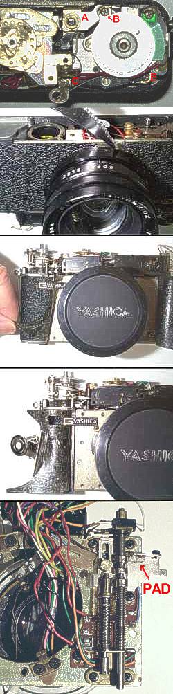
With the top cover removed, you will see a metal plate A that is engaged in the shutter release rod assembly and part of which wraps around the post B. In order to remove the lens assembly in the next step, the metal plate that partially wraps post "B" needs to be free to come out with the shutter release assembly. This requires removing the screws holding the frame counter shown as B, C, E. To ease the removal of the frame counter assembly, remove screw from the top of the post holding the bracket located to the rear and right of the frame counter, then loosen screw C just enough to swing the bracket out of the way, then refasten it. When the frame counter assembly is lifted out, it will be possible to unscrew the post that is below screw "B". This post has a slot in the top, so a screw driver can be used. Do not use a plier. This would squash the hollow inside and destroy the threads. Observe the small spring engaging the double exposure swivel, see how it engages and do not allow it to fly out and get lost.
The next step is to find a knife which is not too sharp, so you don't cut yourself or the plastic skin covering. Carefully begin peeling back the skin around the lens. It is possible to start at the straight edge of the camera sides, but if you slightly disfigure the skin it will show badly when it is cemented down again. On the other hand the curve around the lens is more easily stretched into place invisibly when you are done. Notice that I started at the bottom which is even less noticeable....just in case. Your Choice.
As you progress by slowly moving back the skin, you can keep the loose end out of your way by attaching a file clip to it as shown. Continue to peel back the covering on both sides until you are passed the edge of the lens mounting plate to the body. Do not pull the skin back further as the remaining portion will keep you in alignment for reattaching it later. On the left the Logo that is attached to the body covers one of the screws. Carefully remove this with a single edge razor blade. Note that the skin is factory cut out to fit around the logo. Now remove the 2 screws on each side and gently pry up on the edge of the plate with a small screw driver until the plate lifts. Gently lift the plate a short distance and note that there are 2 wires attached to the lens assembly from the body. Disconnect these and make sure to identify what goes where.
You now have access to the "Pad of Death". Remove the screw holding the right hand switch rod, and carefully lift out. Take note that the spring around this rod has a hook at the bottom, and how it engages. The damaged pad is shown in the image. The right hand switch rod has been moved out of the way in this view. With Access to the pad, remove all traces of the old one making sure that no bits get dropped into the work. With a clean surface attach the new pad with fresh contact cement or crazy glue [cyanocrylate]. Never apply glue from the tube directly, it may run out unexpectedly where it is not wanted. Apply to a nail or toothpick first and work it from there. It is also a good idea to test the adhesion of the pad material to a piece of scrap metal first.
Attach the release rod, wires and remount the lens board assembly. The post with the cross pin at the rear of the lens assembly must engage in the tube with a mating slot on the body. This is the shutter wind engagement. Before you apply the logo and glue back the skin, test the camera. Do not use contact cement to reattach the skin, as you need a slow working glue that gives you time to form the skin gently back into place. A glue stick such as "Elmers" or "uHu" is probably cleanest solution. Note there are many variations in the way the frame counter is fastened and the bracket referred to may be not be on your camera. You have to play it by ear.
Getting the Frame Counter to reset: One of the related events that occurs when the foam light & dust seal starts to rot is that the gummy foam will prevent the frame counter from resetting to zero when the rear door is opened to load a new roll of film.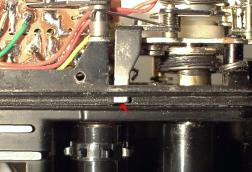
The image shows a portion of the rear track of the camera that normally holds the seal, with the both the foam and the top camera cover removed for clarity. The red arrow points to the tab that lies in the track that holds the foam. As you can see, the tab is a continuation of the lever that resets the frame counter.
A counter that fails to reset can usually be freed up by using a tooth pick to remove any sticky material preventing it from moving freely. This of course also indicates that the time for replacement of the foam seal has arrived. Complete details on the foam replacement follow.
Replacing the Loading Door Light Seals: Many of these cameras have sadly been brought to their knees by the failure of the light & dust gasket. This foam material eventually reverts to it's primordial state, turning this coal-tar derivative to a goo-ey mess. This can prevent the back cover from being opened.  Isopropyl Alcohol sold as "rubbing alcohol" in pharmacies, is an effective solvent of this messy stuff. Use a soft cloth dampened with this, and clean the edges around the door. The image is of an MG-1, one of the later models and Yashica had still not solved this problem. These trailing sticky bits of foam, or what's left of it, can get onto the back of your film as you shoot, and be transferred to the emulsion side as the film is rewound into the cassette The result will be to prevent that area of the image from being developed. It could also transfer to the processing solution and extend it's damage to other films in the bath, much like a virus.
Removal of the residue from the track around the camera body, can be done with patience. Moisten the area with a cotten bud dampened with Isopropyl Alcohol. Be sure the bud is not soaking. You don't want this solution to drip into the camera mechanism or onto the lens. After a couple of minutes begin to gently dig out the old foam using a flat tooth pick. Wipe it clean as you go along, re-applying the solvent from time to time. The fabric strip attached to the body at the location of the hinge should NOT be removed. Clean this gently. Protect the the back door from dust & light entry with black tape if you need to use the camera until you can get this replaced. On the GL there is no foam on the lower track of the camera body. A strip of what I believe to be velour, is attached the the bottom track in the door of this model. Since the only GL that I have come across has this sealer missing, and only the glue residue remains visible, this is a best guess on my part. This model has such a large overlap of the light trap at the hinge, that there is no foam seal between the door and the flange attached at the end of it.
If your Yashicas has a thin strip of velour at the hinge of the door, Diana Seeber came up with a brilliant idea. Visit your local Mini Lab and ask for an empty 35mm cassette. The lip that the film passes through is lined on both sides with exactly the right material that you need and may never find elsewhere.
For those who are reviewing this that intend to replace the foam on a Single Lens Reflex camera [SLR], do not overlook replacing the foam mirror bumper. Use extreme care not to get into contact with the Front Surface Mirror, and prevent bits of rotting foam from falling on the mirror during the restoration.
Complete illustrated details for cutting and installing the foam strips follow. Although most photographers seem to be dedicated do-it-yourselfers, those who would prefer to get precut foam replacement kits can contact Jon Goodman for details at jgood21967@aol.com for details.
Here's how to make your own seals: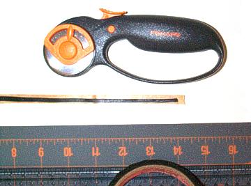 My attempts to cut bulk foam with an Exacto knife left a lot to be desired. In searching for a better solution I came across the left over roll of the "Frost King" weather-stripping [available from any hardware store, which I had applied some 30 years ago when the house was built. This dense black foam with a self adhesive backing was still in great shape. The foam is about 10mm wide by 5mm high, a perfect fit for the Yashicas when cut into 2mm wide strips. The strip shown is actually a precise cut but I was unable to prevent it from partly toppling over, so the size seems to vary.
To cut the strips I used a Fiskars 45mm rotary wheel fabric cutter. As a support, the Fiskars self healing mat worked out very well. Just apply a strip of the Frost King to the desired length on the cutting mat. Make use of the adhesive backing to hold it in place in a straight line. If the foam that you are working with has a very strong adhesive backing, it will help in seperating the strips if you first lay the foam on a piece of wax paper [found in most kitchens] and then place it on the mat to be cut. Use a plastic ruler as a guide for the cutting wheel. Place the wheel against the ruler onto the mat and draw it firmly toward and through the the foam. Do not start by pressing down onto the foam. Roll into it ! If you are using the slab foam, your ruler will likely be supported. If using the weather-stripping, place a second strip of foam alongside the one that you plan to cut so that the ruler can lie flat.
It is now fairly easy to press the foam into the track with a small curved wooden pusher or a coin if nothing else suitable is at hand. Note that you will see a small metal tab about one inch [25mm ] in from the right hand edge of the top track. This is the frame counter reset. Be sure not to damage this in cleaning out the track or replacing your new foam gasket, which should be continued under the tab. If you start from the right, cut the strip off just a little longer than the distance to the tab. You will then be able to push the end in under the tab with a flat toothpick. Push down gently on the tab to make sure it can compress the foam enough to activate the reset action of the frame counter. Continue on inserting the begining of the second piece of foam pushed tightly up against where the other piece left off. Due to the fact that this area is near the hinge of the door, that section will be better closed due to the relative angle of closure, so this is not all that fussy. Don't forget to replace the foam on the door itself, as shown in the image above. I used Elmers glue stick gel and it worked well keeping the foam in place and was less messy than most other alternatives to hold the foam to the door.
Weather stripping is available at any hardware store. Be sure not to get the light weight grey stuff. The rotary fabric cutter is available at any sewing center or Walmart. Perhaps a neighbor who sews can lend you one with the board. Better yet, an experienced seamstress will probably be able to do a great job of cutting your strips for you in a flash.
Removing the Front Lens Retaining Ring: Access to the front lens element for purposes of cleaning or replacing a scratched lens in a working camera with a good lens from junker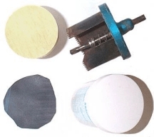 is a subject that often comes up in email to the site.
The front lens retaining ring has two key-ways or slots which suggest the use of a lens spanner tool. This is misleading as the slots are too shallow to be of any use, being purely decorative for all intents and purposes.
To remove the retaining ring without damaging it or it's finish, apply pressure to it with a disk of the correct diameter that should have a non-slip surface. The illustration shows a wood disk cut out. If a suitable power tool like a sabre, band or jig saw is not available, an option is to use an adjustable circle cutting attachment for a drill. Another option is to check for the lid of a jar in your bathroom or under the kitchen sink that may just happen to fit the application. One could also look for an inexpensive product in a supermarket that may be the right fit. Take your camera along when shopping.
The piece of scrap rubber from a car or bicycle tube was glued to the disk with a glue-stick, and then trimmed off. Hold the front rim of the lens barrel firmly as you unscrew the retaining ring counter-clockwise. The diameter of this disk should be about 1 to 2mm less than the size of screw-in filters for that lens. The disk shown is 54mm, and was made for the Yashica GSN.
Restoring Camera Case Snaps: Every now and then one encounters a sad case, [not to make a bad pun] when the Yashicas are passed down enclosed in a case. The new owners or middlemen, are frequenlty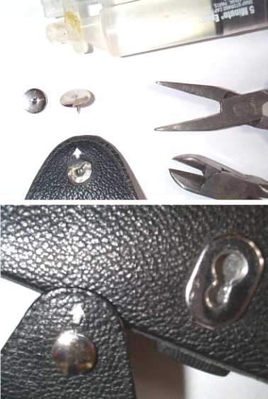 unaware that one of the latch buttons is not a "snap on". In an attempt to force the "snap" open, the cover of the button is usually bent, or breaks off entirely from it's underlying base. It is a tribute to the workmanship, that I have never seen a case where the entire button assembly was ripped off. Doubtless this can happen. As the illustration clearly shows this lower button is in fact a "slide-on / off" intended to make it possible to keep the top cover fastened to the base when the camera is in use, so that it doesn't get misplaced.
A fair amount of space is being devoted to this topic, because of the frequency with which I have encountered this situation. There is fortunately a fix which I have developed that seems to stand up with time.
The first step is to flatten the bent base of the button as nearly as possible. A small wide nose pair of pliers is useful but any small pliers will do. The next step involves a chrome thumb tack. If you check them carefully, you will see that some thumb tacks have the post attachment clearly visible on the top. Shop around until you find the ones which have a perfectly smooth top. Next cut off the pin that extends beyond the tack face. Leaving a small piece of the pin behind serves as an anchor in the next step, and will also prevent the chance of creating a hole in the top.
Cut a slot in two thin pieces of cardboad or better yet out of the thin plastic from a carry-out salad type container, and slide them between the camera case and the button base. This will protect the case from any excess glue. Test the fit of the modified tack face on the base of the case button. When you are satisfied that what remains of the pin is not going to get in the way of a perfect fit, apply epoxy cement with a nail or other thin tool to the base plate, and lay the pin cover on it. As soon as it is clear that no epoxy is going to leak onto the case, slide out the cardboard protective shields before they get glued in place. The more time that you can allow the epoxy to set, the better. As you can see from the magnified "after" shot, a casual observer would never see the repair.
There are limits to the d.i.y. repair of your camera. Many mechanical, electronic and optical adjustments require a great degree of expertise and specialized equipment. If you are searching for a dependable Service Technician to check out any model of Yashica camera,or other brand for that matter, look no further than Mark Hama. He has 40 years of experience and came to Georgia, USA directly from the Yashica Japan factory: USA Phone 770 - 565-1498 or www.markhama.com
In India, we have feedback suggesting the following sources who can handle Yashica camera repairs: In Delhi, India there is an Exclusive Camera Market in 'Chandni Chowk', a popular market of 'Delhi'. You will find a camera store named ' Pritam Studio' . A Yashica owner has recommened them to me. There is also a second camera repair store there, in business for some time named 'Baldev'. Anyone who can provide feedback on them, please contact me.
If you have suggestions for improving the site, or a quick fix that you would like to share,